Search results
Search for "phase diagram" in Full Text gives 56 result(s) in Beilstein Journal of Nanotechnology.
Isolation of cubic Si3P4 in the form of nanocrystals
Beilstein J. Nanotechnol. 2023, 14, 971–979, doi:10.3762/bjnano.14.80

- synthesized either under atmospheric or high pressure. Since pseudocubic Si3P4 is bound to be metastable according to the phase diagram [8], any method of its synthesis must involve out-of-equilibrium conditions. The majority of theoretical studies on numerous Si3P4 phases have shown pseudocubic (tetragonal


Polymer nanoparticles from low-energy nanoemulsions for biomedical applications
Beilstein J. Nanotechnol. 2023, 14, 339–350, doi:10.3762/bjnano.14.29

- ricinoleamidopropyltrimonium methosulfate + Kolliphor® EL + 6 wt % ethyl cellulose in ethyl acetate, an increase in the area of the nanoemulsion region in the phase diagram was observed [47]. The average nanoparticle size also slightly decreased (from 45 to 40 nm) when water was replaced by HEPES solution as the aqueous phase
- [58]. The region for nanoemulsion formation in the phase diagram changes with the electrolyte (PBS) concentration (Figure 4a). There seems to be an optimum value for which this region is the largest, and the colloidal stability is maximum. Note that the presence of electrolyte is expected to reduce
- concomitant shift of the liquid crystalline phase in the middle of the phase diagram (and also in the middle of the water dilution path). The average hydrodynamic diameter of the nanoemulsion droplets increases from ca. 20 to ca. 140 nm when the PLGA concentration is increased from 0.5 to 4 wt %. However, the


Upper critical magnetic field in NbRe and NbReN micrometric strips
Beilstein J. Nanotechnol. 2023, 14, 45–51, doi:10.3762/bjnano.14.5

- normal-state properties. Therefore, the WHH curves obtained from Equation 1 do not contain any fitting parameter [19][40]. All these quantities together with other superconducting and normal-state properties of the two materials are summarized in Table 1. In Figure 4 the perpendicular H–T phase diagram
- performed. Conclusion We have studied the H–T phase diagram for NbRe and NbReN microstrips. Despite the fact that the two materials show very similar morphological, normal-state, and superconducting properties, different results are obtained for the Hc2⟂(T) behavior. In particular, while for NbRe the
- in the parallel geometry. The field increases from μ0H = 0.007 to 5 T. (e, f) ΔTc field dependence of (e) the NbRe and (f) the NbReN microstrip for the perpendicular (black squares) and parallel (red circles) geometries. (a, b) H–T phase diagram of (a) the NbRe and (b) the NbReN microstrip. Black


Atmospheric water harvesting using functionalized carbon nanocones
Beilstein J. Nanotechnol. 2023, 14, 1–10, doi:10.3762/bjnano.14.1

- ). Molecular dynamics simulations were performed using the LAMMPS [48] package using an NVT ensemble with a timestep of 0.1 fs. The TIP4P/2005 [49] water model was used since it provides a satisfactory description of self-diffusion coefficient [50], phase diagram, vapor–liquid equilibria [51][52], vapor


Temperature and chemical effects on the interfacial energy between a Ga–In–Sn eutectic liquid alloy and nanoscopic asperities
Beilstein J. Nanotechnol. 2022, 13, 817–827, doi:10.3762/bjnano.13.72

- –In–Sn. The phase diagram of the Au–In alloy system is similar to that of Au–Ga. However, the difference is that the eutectic formed between In and AuIn2 lays at 156 °C, higher than the maximum temperature applied during our measurements. Finally, the Au–Sn system shows no solubility of Au in Sn and


Experimental and theoretical study of field-dependent spin splitting at ferromagnetic insulator–superconductor interfaces
Beilstein J. Nanotechnol. 2022, 13, 682–688, doi:10.3762/bjnano.13.60

- effect at a ferromagnetic insulator–superconductor (FI–S) interface. The calculations are based on the boundary condition for diffusive quasiclassical Green’s functions, which accounts for arbitrarily strong spin-dependent effects and spin mixing angles. The resulting phase diagram shows a transition
- states per volume is given as We now discuss the self-consistency relation for different values of the parameter ε’. Figure 2 shows the phase diagram for values ε’ = [100–0.1], which for a d = 10 nm aluminium layer roughly translates into fractions r = [1–0.001]. The plotted curves are the phase
- new phase diagram that strongly depends on the spin mixing angle and includes a crossover from a first- to a second-order phase transition. We applied our theory to our experiment measuring the differential conductance in an EuS–Al bilayer. In the experiment, enhanced spin splitting of the density of


Sodium doping in brookite TiO2 enhances its photocatalytic activity
Beilstein J. Nanotechnol. 2022, 13, 599–609, doi:10.3762/bjnano.13.52

- bandgap values of these four samples. Structural phase diagram, chemical composition, and morphology The crystal structure of samples calcinated at 300–900 °C was characterized by powder X-ray diffraction (XRD), as shown in Figure 3a. The sample calcinated at 300 °C is a mixture of brookite (B) and
- activity of these samples. Quantitative phase analysis of X-ray diffraction patterns provides the structure phase diagram, as shown in Figure 3b. It indicates that the weight fraction of the brookite phase can be up to 82% when samples were calcinated at 500 °C. Note that the sample at 600 °C precipitated
- transform into the Na2Ti6O13 structure, the content of sodium in the brookite NaxTi1−xO2 can be estimated when Na2Ti6O13 is written as Na0.25Ti0.75O1.625 (i.e., xmax = 0.25), which is consistent with I. Keesmann's phase diagram [30]. To verify the refined crystal structure, we extracted the atomic pair


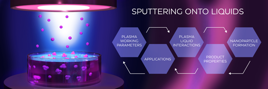
Sputtering onto liquids: a critical review
Beilstein J. Nanotechnol. 2022, 13, 10–53, doi:10.3762/bjnano.13.2


Measurement of polarization effects in dual-phase ceria-based oxygen permeation membranes using Kelvin probe force microscopy
Beilstein J. Nanotechnol. 2021, 12, 1380–1391, doi:10.3762/bjnano.12.102

- according to the Fe3−xCoxO4 phase diagram [10]. For electrical conductivity measurements, the samples were burnished using sanding paper (1200 graining). For KFPM measurements, the samples were embedded in epoxy resin and polished to mirror using diamond polishing paste. The roughness of the polished


Chemical vapor deposition of germanium-rich CrGex nanowires
Beilstein J. Nanotechnol. 2021, 12, 1365–1371, doi:10.3762/bjnano.12.100

- characteristics, their thermodynamic properties hint at quantitatively and qualitatively different behavior of their metal alloys. Therefore, germanides as counterparts of silicides have been gradually becoming a topic of current research. Thermodynamic properties of chromium germanide CrGex, that is, the phase
- diagram [2] and Gibb’s energies [3], were determined. In other works, the crystallographic phases Cr3Ge, Cr5Ge3, Cr11Ge8, CrGe, and Cr11Ge19 were synthetized using chemical vapor transport [4]. Also, Cr11Ge19 in the form of large single crystals was obtained using a two-zone vertical gradient freeze


Spontaneous shape transition of MnxGe1−x islands to long nanowires
Beilstein J. Nanotechnol. 2021, 12, 366–374, doi:10.3762/bjnano.12.30

- (NW) by SAED or by inferring from the interplanar distance was not possible because of the complexity of the Ge/Mn phase diagram. These results show that the NW is monocrystalline and epitaxially grown on the substrate [38]. The question is to understand how these Mn-rich Ge–Mn NWs are formed under


Superconductor–insulator transition in capacitively coupled superconducting nanowires
Beilstein J. Nanotechnol. 2020, 11, 1402–1408, doi:10.3762/bjnano.11.124

- less than 2. As a result, two superconducting wires become insulating as soon as they are brought sufficiently close to each other. This remarkable physical phenomenon is illustrated by the phase diagram in Figure 2b. In order to complete this part of our analysis, we point out that transport
- λ22 = 2. b) Phase diagram for two capacitively coupled superconducting nanowires with λ1 = 2.01 and λ2 = 2.03. Both curves λ11(Cm) and λ22(Cm) decrease and cross the critical line λc = 2 with increasing mutual capacitance, Cm. Funding We acknowledge partial support by RFBR Grant No. 18-02-00586. AGS


Proximity effect in [Nb(1.5 nm)/Fe(x)]10/Nb(50 nm) superconductor/ferromagnet heterostructures
Beilstein J. Nanotechnol. 2020, 11, 1254–1263, doi:10.3762/bjnano.11.109

- the transition seen by SQUID (inset in Figure 4b). Figure 6b shows the (H,T) phase diagram for sample s3. The superconducting transition can be well described by the expression Tc2(H) = Tc2(0) [1 − (H/Hc2(0))2] with Hc2(0) = 12 kOe. This expression can be re-written in the well known form for 2D


![[Graphic 13]](/bjnano/content/inline/2190-4286-11-109-i17.svg?max-width=637&scale=1.18182) ) substrate, (b) the Pt cap layer, and the Nb buffer layer grown at...
) substrate, (b) the Pt cap layer, and the Nb buffer layer grown at...


![[Graphic 16]](/bjnano/content/inline/2190-4286-11-109-i20.svg?max-width=637&scale=1.18182) (T) for the samples s4 (black) and s3 (red) in the vicinity of the superconducting transition m...
(T) for the samples s4 (black) and s3 (red) in the vicinity of the superconducting transition m...
Multilayer capsules made of weak polyelectrolytes: a review on the preparation, functionalization and applications in drug delivery
Beilstein J. Nanotechnol. 2020, 11, 508–532, doi:10.3762/bjnano.11.41

- al. by using a combination of theory, simulation and experiments on the arbitrary sequence of charges [41]. The results indicated that an increase in charge fraction and blockiness generally leads to an increase in the two-phase region of the phase diagram, thereby showing enhanced phase separation


Synthesis of nickel/gallium nanoalloys using a dual-source approach in 1-alkyl-3-methylimidazole ionic liquids
Beilstein J. Nanotechnol. 2019, 10, 1754–1767, doi:10.3762/bjnano.10.171

- experimentally [30][31] and reasoned by theory [32]. The phase diagram of Ni/Ga shows nine different Ni/Ga phases (Supporting Information File 1, Figure S1) [33][34][35][36]. In a comparison of the CO2 hydrogenation abilities of NiGa (β), Ni3Ga (α) and Ni5Ga3 (δ) high selectivities towards the formation of
- particles see Supporting Information File 1, Figure S5, bottom). The presence of the Ga-rich phases Ni3Ga4, Ni2Ga3, Ni3Ga7 and NiGa5, which exist in the Ni/Ga phase diagram can be excluded by SAED measurements (for comparison see Supporting Information File 1, Table S1). Quantification of the EDX spectrum


Magnetic segregation effect in liquid crystals doped with carbon nanotubes
Beilstein J. Nanotechnol. 2019, 10, 1464–1474, doi:10.3762/bjnano.10.145

- straight lines show the first-order phase transition. The calculations were carried out for σ = 5, γ = 0.2, k = 1.5 and various values of the segregation parameter κ. The orientation phase diagram for the selected parameters is shown in Figure 2. The value of the second-order transition field hc = 2.824


Transport signatures of an Andreev molecule in a quantum dot–superconductor–quantum dot setup
Beilstein J. Nanotechnol. 2019, 10, 363–378, doi:10.3762/bjnano.10.36

- , which allow one to identify and quantify the dominant non-local term. In particular, we describe the ground-state properties (phase diagram, average electron occupation) of the system, the zero-bias conductance describing electron transport through the device in the presence of tunnel-coupled normal
- mechanisms as individual Hamiltonian terms, from the microscopic model. Then, we analyze the ground-state properties, and the phase diagram and average electron occupation of the QD–SC–QD system. Subsequently, we outline the transport model describing the setup where each QD is coupled to a normal lead
- effectively tune the ratio of these parameters. The left column of Figure 2 shows the phase diagram, the middle column shows the zero-bias conductance of QDL, and the right column shows the average electron occupation of QDL for different ΓCAR, γEC and tLR values. Note that for all cases the local pairing


Graphene–graphite hybrid epoxy composites with controllable workability for thermal management
Beilstein J. Nanotechnol. 2019, 10, 95–104, doi:10.3762/bjnano.10.9

- facilitate the optimal design of materials for thermal management, we constructed a ‘concentration–thermal conductivity–viscosity phase diagram’. This hybrid approach thus offers solutions for thermal management applications, providing both finely tuned composite thermal properties and workability. We
- filler contribute valuable design parameters to the thermal conductivity and the viscosity of the composite (Figure 4). Therefore, to provide a practical tool for optimizing the hybrid polymer composite composition, we constructed a phase diagram in which equi-viscosity lines are drawn over a TC vs
- graphite–GNP plot (Figure 5). A similar approach was previously employed for a silicone rubber system [41]. The phase diagram facilitates the design of composites containing a graphite–GNP mixture with a particular thermal conductivity, while simultaneously enabling the control of the viscosity. In


Hydrogen-induced plasticity in nanoporous palladium
Beilstein J. Nanotechnol. 2018, 9, 3013–3024, doi:10.3762/bjnano.9.280

- V, while PdHα disappears at potentials below −0.99 V. Nanostructured materials can exhibit a significant narrowing of the miscibility gap in the phase diagram compared to the bulk metal [33], which can drive the onset of β-phase formation to higher hydrogen concentrations and/or lower potentials


Block copolymers for designing nanostructured porous coatings
Beilstein J. Nanotechnol. 2018, 9, 2332–2344, doi:10.3762/bjnano.9.218

- processes with novel and more sustainable solutions could be a path forward, but the discussion is still open. a) Phase diagram of diblock copolymer predicted by SCMF theory. Reprinted with permission from [41], copyright 2006 American Chemical Society. b) Various microdomain organization patterns of a


Synthesis of hafnium nanoparticles and hafnium nanoparticle films by gas condensation and energetic deposition
Beilstein J. Nanotechnol. 2018, 9, 1868–1880, doi:10.3762/bjnano.9.179

- aggregation-zone lengths of D = 50, 75 and 100 mm. In all cases the majority of the peaks was matched with hexagonal close-packed (hcp) Hf (Figure 3). The hcp structure of the Hf NPs agrees with previous thermodynamic calculations presenting the phase diagram of Hf NPs with the particle size as function of
- air. The hcp structure of the Hf NPs agrees with previous thermodynamic calculations presenting the phase diagram of Hf NPs as a function of particle size and temperature [37]. The shape of Hf NPs confirms the theoretical model proposed in a recent publication by Luo et al. for hcp nanocrystals [53


A zero-dimensional topologically nontrivial state in a superconducting quantum dot
Beilstein J. Nanotechnol. 2018, 9, 1705–1714, doi:10.3762/bjnano.9.162

- current that vanishes at zero temperature. The phase diagram of this system has been already discussed in the literature [34][64][65][66][67][68]. Since we consider here only the weak interacting case, we will not discuss the 0–π transition driven by the presence of strong interaction. A more thorough


Josephson effect in junctions of conventional and topological superconductors
Beilstein J. Nanotechnol. 2018, 9, 1659–1676, doi:10.3762/bjnano.9.158

- here only discuss a few key observations. A full discussion of the phase diagram and the corresponding physics will be given elsewhere. The main panel of Figure 8 shows the critical current Ic vs the bulk Zeeman energy Vx for several values of the chemical potential μ, where the respective critical


![[Graphic 75]](/bjnano/content/inline/2190-4286-9-158-i137.svg?max-width=637&scale=1.18182) = 1 in Figure 6, for different bulk Zeeman fields Vx (in meV) near the crit...
= 1 in Figure 6, for different bulk Zeeman fields Vx (in meV) near the crit...


Robust topological phase in proximitized core–shell nanowires coupled to multiple superconductors
Beilstein J. Nanotechnol. 2018, 9, 1512–1526, doi:10.3762/bjnano.9.142

- lowest energy states are localized on the outer edges of the shell, which strongly inhibits the orbital effects of the longitudinal magnetic field that are detrimental to Majorana physics. Using a tight-binding model of coupled parallel chains, we calculate the topological phase diagram of the hybrid
- wire. One can actually view the wire as a set of n coupled chains, each having a pair of Majorana modes at its ends. On the one hand, this results in a rich phase diagram [29], which means that core–shell nanowires provide an interesting playground for studying topological quantum phase transitions. On
- hosts the zero-energy Majorana modes and one can obtain an additional experimental knob for exploring a rich phase diagram and observing potentially interesting low-energy physics. The rest of this article is organized as follows. We first describe the coupled-chains tight binding model that we use in


![[Graphic 30]](/bjnano/content/inline/2190-4286-9-142-i36.svg?max-width=637&scale=1.18182) ) = 0 and
) = 0 and ![[Graphic 31]](/bjnano/content/inline/2190-4286-9-142-i37.svg?max-width=637&scale=1.18182) = 0. The white areas are t...
= 0. The white areas are t...


![[Graphic 40]](/bjnano/content/inline/2190-4286-9-142-i46.svg?max-width=637&scale=1.18182) ) ≠ 0 and
) ≠ 0 and ![[Graphic 41]](/bjnano/content/inline/2190-4286-9-142-i47.svg?max-width=637&scale=1.18182) = 0. The white areas are topol...
= 0. The white areas are topol...

![[Graphic 50]](/bjnano/content/inline/2190-4286-9-142-i56.svg?max-width=637&scale=1.18182) ) ≠ 0 and
) ≠ 0 and ![[Graphic 51]](/bjnano/content/inline/2190-4286-9-142-i57.svg?max-width=637&scale=1.18182) 1 = 0,
1 = 0, ![[Graphic 52]](/bjnano/content/inline/2190-4286-9-142-i58.svg?max-width=637&scale=1.18182) 3 = π/2,
3 = π/2, ![[Graphic 53]](/bjnano/content/inline/2190-4286-9-142-i59.svg?max-width=637&scale=1.18182) 5 = −π/2. T...
5 = −π/2. T...

![[Graphic 65]](/bjnano/content/inline/2190-4286-9-142-i71.svg?max-width=637&scale=1.18182) ) ≠ 0 and
) ≠ 0 and ![[Graphic 66]](/bjnano/content/inline/2190-4286-9-142-i72.svg?max-width=637&scale=1.18182) 1 = π/2,
1 = π/2, ![[Graphic 67]](/bjnano/content/inline/2190-4286-9-142-i73.svg?max-width=637&scale=1.18182) 3 = −π/2,
3 = −π/2, ![[Graphic 68]](/bjnano/content/inline/2190-4286-9-142-i74.svg?max-width=637&scale=1.18182) 5 = π/2, and ...
5 = π/2, and ...


![[Graphic 79]](/bjnano/content/inline/2190-4286-9-142-i85.svg?max-width=637&scale=1.18182) = 3 of a triangular wi...
= 3 of a triangular wi...


Induced smectic phase in binary mixtures of twist-bend nematogens
Beilstein J. Nanotechnol. 2018, 9, 1297–1307, doi:10.3762/bjnano.9.122

- binary phase diagram for mixtures of imino-linked cyanobiphenyl (CBI) dimer and imino-linked benzoyloxy-benzylidene (BB) dimer shows two distinct domains. While mixtures containing less than 35 mol % of BB possess a wide temperature range twist-bend nematic phase, the mixtures containing 55–80 mol % of
- BB exhibit a smectic phase despite that both pure compounds display a Iso–N–NTB–Cr phase sequence. The phase diagram shows that the addition of BB of up to 30 mol % significantly extends the temperature range of the NTB phase, maintaining the temperature range of the nematic phase. The periodicity
- full composition range between CBI and BB, however the most surprising was detection of the smectic phase for the mixtures containing 55–80 mol % of BB. Thus the phase diagram of the binary BB–CBI mixture can be envisaged as two distinct puzzling domains, one enriched with CBI and the other enriched


